Specifications
- Size: 4cm x 8.4cm x 0.5cm
- MCU: RP2040
- Pyro Channels: 2
- Peripherals:
- Micro SD card slot up to 32GB
- Ublox MAX-M10S GNSS receiver
- MPU-6050 IMU
- BME280 barometer
- RFM95W radio module
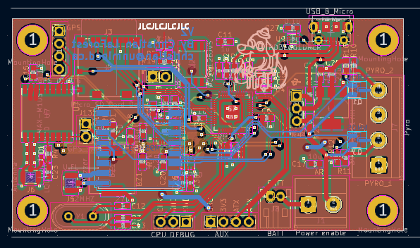
It is unfair to call Northstar V2 a new version of the flight computer, as it is more of an overhaul of the original V1. The first difference is that the integrated physical memory was removed. This was because it was not crucial to the function of the board, as well as it made for an easier time laying out the board. Another difference in the layout of the board is the removal of the power switcher IC, as it is also unnecessary. Other than making sure that some components had the right passives, there were no real changes between the schematics.
For the PCB layout, a new approach was taken in an attempt to reduce the "spaghetti-ness" of the traces. What I did was group the peripherals with their passive components, and initially routed their local traces. From there I placed them on the board. By doing that, I managed to reduce the size of the entire board slightly, it also did indeed help with the clutter.
Another issue with the V1 was that the holes meant for debug pins were accidentally made to be too small, such that any of the pin headers I had would not fit, meaning that even if it did work, I would not be able to program it, so that was also fixed on this version.
After getting the new components and the PCBs, I put it all together, only to find out that I had forgotten to route the run pin on the RP2040, so it would not run any programs that were placed on it. Another issue was that the USB lines were not working, which could be for several reasons, the most likely of which is that the line impedance is not correct, which could be fixed with new resistors, however, the board could still be programmed via the SWD interface.
Although the board was working, and running code, an issue arose where all of the devices on the I2C lines would not respond. I had no clue why it could be, so I used an oscilloscope at my university to try and probe the issue. For some reason, the clock line was constantly pulled high, which after a long time of pondering and looking at datasheets, was caused by the GPS module being placed backwards. This was confirmed when the second board worked and the GPS was placed correctly.