Specifications
- Size: 4.6cm x 7.8cm x 0.5cm
- MCU: RP2040
- Pyro Channels: 2
- Peripherals:
- 16MB Onboard memory
- Micro SD card slot up to 32GB
- Ublox MAX-M10S GNSS receiver
- MPU-6050 IMU
- BME280 barometer
- RFM95W radio module
When I entered university, I did not know that there was a rocketry team there. This was because they had only started the year prior. During the information night that they had before applications, I learned that the team was interested in possibly designing their telemetry systems to get information from the rocket. At first, I was intrigued by this proposition, as well as since I already enjoyed rockets and electronics, I decided to apply to the team. After making it past the preliminary application process, I was given an interview time. To hopefully increase my chances of getting onto the team, I decided to put together a prototype telemetry system using two Arduinos and two simple radio modules in two weeks. During midterms. Although possibly not the brightest use of my time, it paid off in the end as I was accepted to the team.
After Joining Ontario Tech Space And Rocketry, I had assumed that we were going to be designing our flight systems right off the bat, allowing me to finally learn PCB design. That was until I found out that the designing of custom systems was going to have to wait until the next year.
Since we wouldn’t be making anything "custom" until the future, I decided to take matters into my own hands and make my flight computer.
For me to make a flight computer, I first needed to design a flight computer. To design a flight computer, I needed software to design it. For this, I chose KiCAD, due to its being open source, as well as the large community support and ease of use. Now that I had a pot, I needed to figure out what would control the board.
When it comes to microcontrollers, there are a lot on the market, which all have different levels of support, complexity, ease of use, power draw, number of cores, and more. All of these criteria make finding the perfect MCU nigh impossible, so instead of searching for the perfect one, I chose one that would be reasonable: the RP2040, which is the MCU of the relatively new, pretty widely used Raspberry Pi Pico. I mainly chose it because it seemed cool, but is not only cheap for its feature set but also in general, allowing me to keep prices down.
Having worked with Arduinos and several of its peripherals in the past, I had a relatively good understanding of how the common communications protocols worked, and what was theoretically required for them to run well. With those in mind, I came up with a schematic that I was happy with, especially as it was my first time doing anything of the sort.
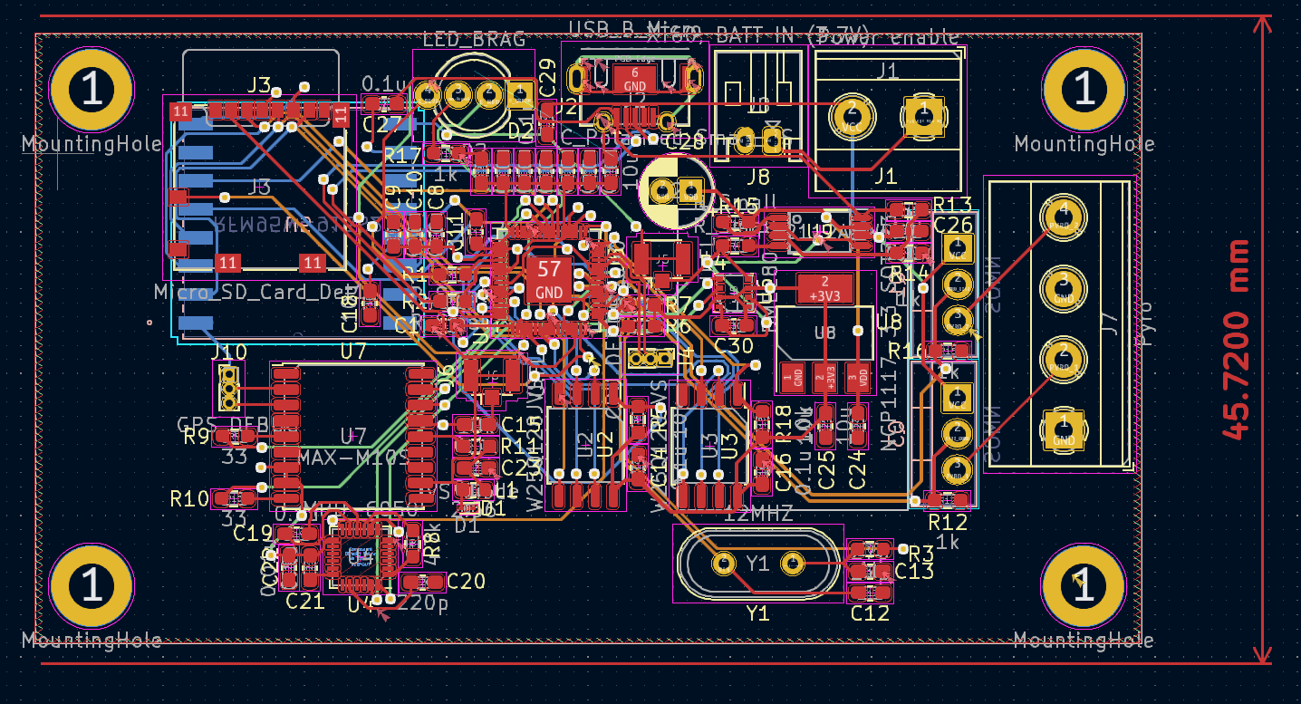
After designing the schematic, the next part is placing the components into a PCB drawing. As I had no idea where to start, I started with the MCU and placed all of the sensors around it. With this design, I had to keep in mind the possibility that I would have to hand-solder all of the components since at the time I was unsure of a way for me to reasonably reflow the entire board. I also tried to put all of the components onto the top, making it a little easier to do the whole assembly process. With those in mind, I came up with a design that I was reasonably happy with, although, in hindsight, the design was spaghetti.
After ordering the boards and components, I went about assembling one of them. Thankfully between ordering the components and getting them, I found that I had an induction heat plate that I could use for reflowing the board, which will make the assembly significantly easier. With the board (almost) fully assembled, I went about testing it. I kept the pyro MOSFETs and radio module off of the board because I was wary that I would have to re-solder or remove components.
When I first connected the board to my computer, it immediately got VERY hot. Because of this, I had to immediately unplug it. From an educated guess working my way up the power path, I surmised that the component that was likely causing the problem was an IC that works to switch between battery power and USB power. From the assumption that I had messed up its layout, I removed it from the circuit, jumped the connections required for the board to work with USB, and plugged it back in, only for the next component in the circuit to start heating; the linear regulator. I was perplexed as to why the circuit kept heating up, so I did some testing and realized that I put the wrong capacitor for the regulator, causing it to not provide the expected voltage, I switched it for the right one and tried for the third time.
The third attempt lasted longer until the MCU started heating up, so I did some research only to find out that the traces for power on the board were too small. This was because I incidentally changed the default trace width to accommodate for the small pins on the RP2040, and had assumed that daisy chaining all of the components together would be adequate.
Although Northstar V1 would never work, this project let me learn a lot about PCB design, which I can apply to future projects.